Toyota Corolla: Child restraint systems / Child restraint system fixed with an ISOFIX lower anchorage
■ ISOFIX lower anchorages (ISOFIX child restraint system)
Lower anchorages are provided for the outboard rear seats. (Marks displaying the location of the anchorages are attached to the seats.)
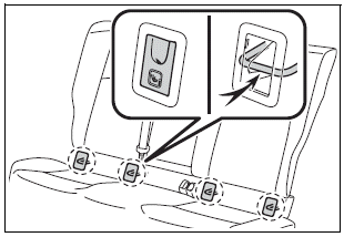
■ When installing in the rear outboard seats
Install the child restraint system in accordance to the operation manual enclosed with the child restraint system.
If the child restraint system on hand is not within the “universal” category (or the necessary information is not in the table), refer to the “Vehicle List” provided by the child restraint system maker for various possible installation positions, or check the compatibility after asking the retailer of the child seat. (®P.55, 56)
1. If the head restraint interferes with your child restraint system, and the head restraint can be removed, remove the head restraint. Otherwise, put the head restraint in the upper most position. (®P.136)
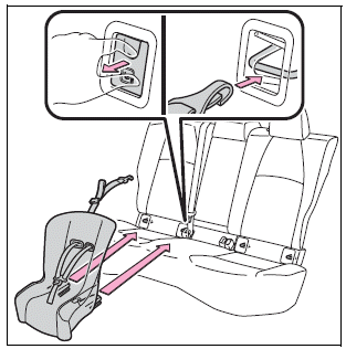
With flexible lower attachments
2 Remove the anchorage covers, and install the child restraint system to the seat.
The bars are installed behind the anchorage covers.
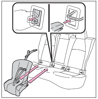
► With rigid lower attachments
2. Remove the anchorage covers, and install the child restraint system to the seat.
The bars are installed behind the anchorage covers.
3. If the child restraint has a top strap, follow the child restraint manufacturer’s operation manual regarding the installation, using the top strap to latch onto the top strap anchorage.
4. After installing the child restraint system, rock it back and forth to ensure that it is installed securely.
■ When installing in the rear center seat
There are no lower anchorages behind the rear center seat. However, the inboard lower anchorages of the outboard seats, which are 15.6 in. (396 mm) apart, can be used if the child restraint system manufacturer’s instructions permit use of those anchorages with the anchorage spacing stated.
Child restraint systems with rigid lower attachments cannot be installed in the center seat. This type of child restraint system can only be installed in the outboard seat.
■When using a “MIDI 2”
Adjust the support leg and ISOFIX connectors as follows:
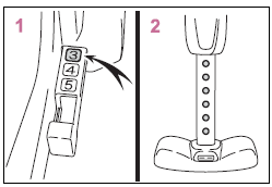
1 Lock the ISOFIX connectors where number 3 can be seen.
2 Lock the support leg where 6 holes can be seen.
WARNING
■When installing a child restraint system
Observe the following precautions. Failure to do so may result in death or serious injury.
- When using the lower anchorages, be sure that there are no foreign objects around the anchorages and that the seat belt is not caught behind the child restraint system.
- Follow all installation instructions provided by the child restraint system manufacturer.
- Never attach two child restraint system attachments to the same anchorage. In a collision, one anchorage may not be strong enough to hold two child restraint system attachments and may break. If the lower anchorages are already in use, use the seat belt to install a child restraint system in the center seat.
- When securing some types of child restraint systems in rear seats, it may not be possible to properly use the seat belts in positions next to the child restraint without interfering with it or affecting seat belt effectiveness. Be sure your seat belt fits snugly across your shoulder and low on your hips. If it does not, or if it interferes with the child restraint, move to a different position. Failure to do so may result in death or serious injury.
- If the seat is adjusted, reconfirm the security of the child restraint system.
 Child restraint system fixed with a child restraint LATCH anchor
■ Child restraint LATCH anchors
LATCH anchors are provided for the outboard rear seat. (Marks displaying the
location of the anchors are attached to the seats...
 Using an anchor bracket (for top tether strap)
■ Anchor brackets (for top tether strap)
Anchor brackets are provided for each rear seat.
Use anchor brackets when fixing the top tether strap.
► Seats with an adjustable type head restraint
A - Anchor brackets<> B - Top tether strap
► Seats with an integrated type head restraint
A - Anchor brackets<> B - Top tether strap
■ Fixing the top tether strap to the anchor bracket
In..
Other information:
Toyota Corolla 2019-2025 Owners Manual: Towing with a wheel-lift type truck
► From the front Release the parking brake. Vehicles with electric parking brake: Turn automatic mode off. ► From the rear Use a towing dolly under the front wheels. NOTICE ■ Towing with a sling-type truck Do not tow with a sling-type truck to prevent body damage. Using a flatbed truck When using a flat-bed truck to transport the vehicle, use tire strapping belts. Refer to the owner's ma..
Toyota Corolla 2019-2025 Owners Manual: Seat belt pretensioners (front seats)
The pretensioners help the seat belts to quickly restrain the occupants by retracting the seat belts when the vehicle is subjected to certain types of severe frontal or side collision or a vehicle rollover. The pretensioners do not activate in the event of a minor frontal impact, a minor side impact or a rear impact. ■Replacing the belt after the pretensioner has been activated If the vehicl..
Categories
- Manuals Home
- 12th Generation Corolla Owners Manual
- Sensors
- Transfer contacts from device
- Alarm
- New on site
- Most important about car
Engine immobilizer system
The vehicle’s keys have built-in transponder chips that prevent the engine from starting if a key has not been previously registered in the vehicle’s on-board computer.
Never leave the keys inside the vehicle when you leave the vehicle.
This system is designed to help prevent vehicle theft but does not guarantee absolute security against all vehicle thefts.
Operating the system
